We have seen considerable global activity focused on developing glass core substrate assemblies and interposers, yet, as some of us have often mentioned, we have seen little in the way of reliability data for any modules built from these substrates.
IFTLE considers the work of Absolics (the US division of Korea’s SK company) as the furthest along in such work since it is actually in the process of finishing the installation of a production line in Covington Ga. (See IFTLE 587 and IFTLE 601)

At the recent IMAPS meeting in Boston, Unimicron’s John Lau – certainly one of the top five packaging experts in the world – delivered a presentation on “Solder Joint Reliability of Glass Core Substrate Assemblies”.
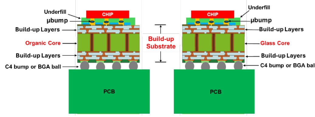
Unimicron’s finite element modeling work compared the thermal fatigue reliability between flip chip micro solder joints on a glass core substrate and C4 solder joints to the PCB. These are then compared to the same structure with conventional organic core build up structure. Structures are shown in Figure 1.

In this study, the solder cap of the micro bump is made of Sn0.7Cu (mp 227°C) and the solder of the C4 bump is Sn3Ag0.5Cu (mp 217). The chip is 10mm x 10mm x 350µm thick. There are two build up layers on each of the cores top and bottom side. The dielectric layers are 5µm thick and the copper layers are 3µm thick.
Results
Overall Warpage
For the organic core substrate assembly at 85°C the PCB expands more than the organic package substrate and the silicon chip and the stress results in a convex warpage. At -40°C the PCB shrinks more than the organic package and the silicon chip and the resultant warpage is concave.
For the PCB assembly with the glass core substrate at 85°C the structure is convex and at -40°C the structure is concave – just like the organic core substrate – however the magnitude of the deformations is different. The maximum deformations of the glass core substrate structure are 73µm at 85°C and -103µm at -40°C while the organic core substrate reveals 58µm and 69µm respectively for the same temperatures. Basically, the larger the thermal coefficient expansion (TCE) mismatch between the buildup package substrate and the PCB, the larger the deformation.
Bump Stress
When studying stress in bumps, one looks to the corner bumps where the stress is maximized.
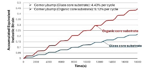
They examined the inelastic strain build up between the corner micro bumps for the organic core vs glass core substrates and found that the maximum strain for the glass core is smaller than for the organic core (Figure 2).

This is because the TCE mismatch between the glass core substrate and silicon chip is smaller than that of the organic core substrate and the silicon chip.
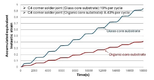
Unimicron then looked at the strain distributions for the corner C4 solder joints. The results are shown in figure 3. Results show that the glass core substrate C4 bump strain is higher than the organic core substrate.

This is because the TCE mismatch between the glass core substrate and the PCB is larger than the organic core substrate and the PCB.
Conclusions:
- Warpage of the overall structure with the glass core substrate is greater than with the organic core basically due to the larger TCE mismatch.
- Inelastic strain in the µbump solder joint is ~ 2X smaller in the glass core substrate because the TCE mismatch between the chip and the glass core is smaller.
- Inelastic strain in the C4 solder joint is > 2X larger for the glass core substrate because of the larger TCE mismatch.
Which of these results is most important will depend on the details of the overall structure but this modeling certainly shows that use of these glass core substrates can definitely have an impact on overall component reliability.
For all the latest on Advanced Packaging stay linked to IFTLE…


